I will be using Raspberry PI's I2C interfaces for connecting the modules.
The hardware that I will be using has as follows:
1. Raspberry PI Model B, Version 2.

Since Ethernet connectivity is not needed and in order to minimize power consumption, model A could be used in field. That said, during development and testing, model B will be used.
2. The digital Compasses will be based to a HMC5883L Triple Axis Compass Magnetometer Sensor Module:

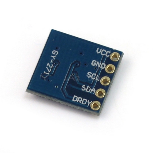
This module is I2C based.
I2C bus enables multiple devices to get connected to the master device (in this case the Raspberry PI), as shown in the following image:

The problem is that on these devices I cannot change the address, and I need to connect 2 of them!
Luckily, Raspberry PI Model B V2 (and any Model A) has available a second I2C bus, as shown in the Raspbery Schematics and described here.
So the simple solution is to connect each of the magnetometers to a different I2C bus (problem solved!).
3. The existing apparent wind direction indicator produces two analogue values. In order to read them I will use an I2O-based A-to-D converter, probably this one:
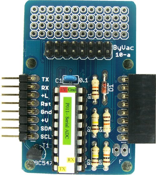
Information on using and programming this module are shown here.
This is a 8 port A/D converter, for the apparent wind direction I will be using 2 (6 left, one will be used for power consumption measurement, see later!)
The relation between this values and the wind direction, will be mapped manually, by means of testing.
(UPDATE: I bought one of the above but couldn't make it work, so I opted for using a Adafruit ADS1115 instead. The Pi Chips PO11 ADC not working could be of my fault, I will investigate whenever I find time to do so...)
4. The apparent wind speed is measured by the wind cup rotor that produces a number of pulses per revolution. I intend to feed these signal to a I/O port (via a voltage divider) and use interrupts in order to measure the width of the pulse without wasting precious CPU cycles on the Raspberry.
The actual way to do it is described here.
5. The last essential module is a GPS that will communicate with the Raspberry through the Serial port.
I have bought this SUPERB GPS module:
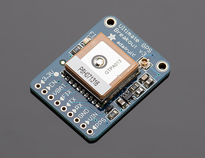

Everything needed for connecting the GPS, programming it and using it can be found here (Thanks Adafruit for everything!)
This concludes the description of the essential modules.
No comments:
Post a Comment