I had complains!
It may not show here, but I had a few friends calling and sending emails, disappointed I diverted from the initial idea and instead of working to the Ship Computer, I wasted time on a battery monitor...
Well, rejoice!
I changed a couple bits and now, the Battery Monitor can get connected to the Ship Computer (when it will be build that is...) and will be used as a probe for suppling data on current and voltage.
How about that?
Friday, 7 March 2014
Monday, 3 March 2014
Arduino-based battery monitor
Hello again!
I started with the Ship Computer last October but had to stop working on it for a couple of months and hoped to start over again in January.
Which, unfortunately I didn't.
The same time I am setting up a trip around Ionian for which I am planning to get going by mid May, that is, less than 2 and a half months away, and I have to prepare the boat and everything.
Which means that probably there won't be much time for software development...
Nevertheless, I absolutely need some of the functionality the ship computer was going to give me, and knowing that probably I won't have the Ship Computer ready for this trip, I started thinking of alternatives.
One thing that I have to have is a battery monitor.
On the boat I have a 120W solar panel for charging a 65AH battery and, if absolutely necessary, I can also use the outboard alternator for additional 60W of battery charging power. As far as consumption goes, I have installed led-based navigation and cabin lights so that will keep the consumption down. Other source of power consumption include the instruments and the autohelm, for which I am particularly worried.
Anyway, since I only carry a single battery, I need to know how much consumption is there, what is the charging current when applicable and the battery voltage.
In order to get this functionality, I used an arduino Pro Mini, a current sensor (similar to this), a voltage divider set up with two resistors and a 16x2 LCD screen connected to I2C.
For powering I used a low cost 6V UBEC like this one: http://r.ebay.com/NQZ0ne
The finished project looks like this:

The source code for the project is very simple and has as following:
#include <Wire.h>
#include <LiquidCrystal_I2C.h>
float amperes=0;
float volts=0;
LiquidCrystal_I2C lcd(0x27, 2, 1, 0, 4, 5, 6, 7, 3, POSITIVE);
void setup()
{
// initialize the lcd
lcd.begin(16,2);
lcd.clear();
lcd.print("Amps=");
lcd.setCursor ( 0, 1 );
lcd.print("Volts=");
}
void clearValues(){
lcd.setCursor ( 6, 0 );
lcd.print(" ");
lcd.setCursor ( 7, 1 );
lcd.print(" ");
}
void showValues(float Amps,float Volts){
clearValues();
lcd.setCursor ( 6, 0 );
lcd.print(Amps,3);
lcd.setCursor ( 7, 1 );
lcd.print(Volts);
}
void loop()
{
// MEASURE CURRENT
// ampere sensor connected to A3
amperes=0;
long temp=0;
//150 reads, 15 usec delay = total 2.25msec
for(int i = 0; i < 150; i++) {
temp+=analogRead(A7);
amperes = amperes + (.0264 * analogRead(A3) -13.51) / 150;
//function calibrated for 5A sensor
delayMicroseconds(15); //15 usec delay for the A2D to "reset"
}
temp/=150;
amperes=(0.0049*(temp-512))/0.185;
//negative on discharge, positive on charge
amperes*= (-1);
//
// MEASURE VOLTAGE
// voltage divider (1/5) conected at pin A2
temp=0;
//150 reads, 15 usec delay = total 2.25msec delay for a measurement
for(int i = 0; i < 150; i++) {
temp+=analogRead(A3);
delayMicroseconds(15); //15 usec delay for the A2D to "reset"
}
temp/=150; // get the average value
volts=temp*5.01*((19.93+6.8)/6.8)/1024.0; // calculate actual voltage
showValues(amperes,volts);
delay(300);
}
The whole setup is simple, works like a charm and is a way to get some limited but needed functionality even if the Ship Computer is not ready in time for the trip.
That said, I hope to be back soon with a post about the ship computer itself!
Thanks for reading,
G.
I started with the Ship Computer last October but had to stop working on it for a couple of months and hoped to start over again in January.
Which, unfortunately I didn't.
The same time I am setting up a trip around Ionian for which I am planning to get going by mid May, that is, less than 2 and a half months away, and I have to prepare the boat and everything.
Which means that probably there won't be much time for software development...
Nevertheless, I absolutely need some of the functionality the ship computer was going to give me, and knowing that probably I won't have the Ship Computer ready for this trip, I started thinking of alternatives.
One thing that I have to have is a battery monitor.
On the boat I have a 120W solar panel for charging a 65AH battery and, if absolutely necessary, I can also use the outboard alternator for additional 60W of battery charging power. As far as consumption goes, I have installed led-based navigation and cabin lights so that will keep the consumption down. Other source of power consumption include the instruments and the autohelm, for which I am particularly worried.
Anyway, since I only carry a single battery, I need to know how much consumption is there, what is the charging current when applicable and the battery voltage.
In order to get this functionality, I used an arduino Pro Mini, a current sensor (similar to this), a voltage divider set up with two resistors and a 16x2 LCD screen connected to I2C.
For powering I used a low cost 6V UBEC like this one: http://r.ebay.com/NQZ0ne
The finished project looks like this:
In this picture:
- #1 is the current sensor
- #2 if the arduino Pro Mini
- #3 is the insulation for the arduino
- #4 is the UBEC with the insulattion sleeve in place
- #5 is the 16x2 LCD screen
#include <Wire.h>
#include <LiquidCrystal_I2C.h>
float amperes=0;
float volts=0;
LiquidCrystal_I2C lcd(0x27, 2, 1, 0, 4, 5, 6, 7, 3, POSITIVE);
void setup()
{
// initialize the lcd
lcd.begin(16,2);
lcd.clear();
lcd.print("Amps=");
lcd.setCursor ( 0, 1 );
lcd.print("Volts=");
}
void clearValues(){
lcd.setCursor ( 6, 0 );
lcd.print(" ");
lcd.setCursor ( 7, 1 );
lcd.print(" ");
}
void showValues(float Amps,float Volts){
clearValues();
lcd.setCursor ( 6, 0 );
lcd.print(Amps,3);
lcd.setCursor ( 7, 1 );
lcd.print(Volts);
}
void loop()
{
// MEASURE CURRENT
// ampere sensor connected to A3
amperes=0;
long temp=0;
//150 reads, 15 usec delay = total 2.25msec
for(int i = 0; i < 150; i++) {
temp+=analogRead(A7);
amperes = amperes + (.0264 * analogRead(A3) -13.51) / 150;
//function calibrated for 5A sensor
delayMicroseconds(15); //15 usec delay for the A2D to "reset"
}
temp/=150;
amperes=(0.0049*(temp-512))/0.185;
//negative on discharge, positive on charge
amperes*= (-1);
//
// MEASURE VOLTAGE
// voltage divider (1/5) conected at pin A2
temp=0;
//150 reads, 15 usec delay = total 2.25msec delay for a measurement
for(int i = 0; i < 150; i++) {
temp+=analogRead(A3);
delayMicroseconds(15); //15 usec delay for the A2D to "reset"
}
temp/=150; // get the average value
volts=temp*5.01*((19.93+6.8)/6.8)/1024.0; // calculate actual voltage
showValues(amperes,volts);
delay(300);
}
The whole setup is simple, works like a charm and is a way to get some limited but needed functionality even if the Ship Computer is not ready in time for the trip.
That said, I hope to be back soon with a post about the ship computer itself!
Thanks for reading,
G.
Friday, 17 January 2014
The Wind Sensor
Hello again!
it's almost 2 months since my last post and believe it or not, I have not abandoned the project.
To say the truth I have been tempted to "postpone" developments and start a couple new ones and actually I have started working on a drone BUT I have to go on with this "Ship Computer" project -if not for anything else- for the simple reason that I need to have it!
So, on my last post I was putting a draft version of the system together using a Raspberry PI as the heart of the system.
I had also mentioned that I was going to use an I2C Analog to Digital converter and I had actually bought a couple -pretty expensive- ones.
The thing is, I thought it over a bit and decided to use a Arduino Pro Mini for interfacing with the Wind Sensor.
The Arduno Pro Mini is this one:
 It is a full-fledged Arduino in a tiny package.
How tiny is tiny?
Tiny enough to look small next to a credit-card sized Raspberry:
 The same time it can be bought from ebay for just a couple euros, making it extremely more cost effective compared to the ADC I was thinking of using while still far more versatile.
So, it was not much of a question really, I was going to use the Arduino in order to get measurements for wind speed and direction.
The actual transducer for getting this measurements was a low cost NASA MARINE masthead unit as shown here.
Two months and something ago I had tried to get in contact with Nasa Marine in order to get some info on this unit but there was not a reply.
So, I had to do a bit of reverse engineering.
The unit terminates on a 5-pin DIN connector, same as the one of the old (pre-nineties) PC keyboard, whose pin layout is as follows:
 Playing a bit with a multimeter, I decoded the signals:
The wind speed would be almost proportional to the rotating speed of the cup rotor, which produced a pulse for a full turn.
Next I attached the masthead unit to a bookcase next to my desk so that I could rotate the windex and the cup rotor:

...and I fed the signals to the Arduino:

 ...and also connected an LCD display so that I would have a quick way to see what was going on.
All I needed was a bit of software, the soul that would make it tick.
I spent a couple of nights and here it is:
It is completely Interrupt Driven (the main loop all it does is to display the readings), it handles smoothing of the analog values, it is a perfect base for I want to do next, which is to set the Arduino as a I2C slave device, connect it to the Raspberry and set up a high-level protocol for their communication.
But more on that next time!
Thanks for reading,
G.
PS
Using the NASA Masthead unit was a dog.
The analog values are not stable enough, they change along with the ambient temperature and the cup rotor only creates a single pulse per revolution. This is a low cost unit and it shows.
Nevertheless, if anyone is thinking of using it in a project, do drop a line, we might exchange notes!
it's almost 2 months since my last post and believe it or not, I have not abandoned the project.
To say the truth I have been tempted to "postpone" developments and start a couple new ones and actually I have started working on a drone BUT I have to go on with this "Ship Computer" project -if not for anything else- for the simple reason that I need to have it!
So, on my last post I was putting a draft version of the system together using a Raspberry PI as the heart of the system.
I had also mentioned that I was going to use an I2C Analog to Digital converter and I had actually bought a couple -pretty expensive- ones.
The thing is, I thought it over a bit and decided to use a Arduino Pro Mini for interfacing with the Wind Sensor.
The Arduno Pro Mini is this one:
How tiny is tiny?
Tiny enough to look small next to a credit-card sized Raspberry:
So, it was not much of a question really, I was going to use the Arduino in order to get measurements for wind speed and direction.
The actual transducer for getting this measurements was a low cost NASA MARINE masthead unit as shown here.
Two months and something ago I had tried to get in contact with Nasa Marine in order to get some info on this unit but there was not a reply.
So, I had to do a bit of reverse engineering.
The unit terminates on a 5-pin DIN connector, same as the one of the old (pre-nineties) PC keyboard, whose pin layout is as follows:
- Pin 1:Pulse per Wind Cups rotation
- Pin 2:GND
- Pin 3:+5V
- Pin 4:Analog output 1
- Pin 5:Analog output 2
The wind speed would be almost proportional to the rotating speed of the cup rotor, which produced a pulse for a full turn.
Next I attached the masthead unit to a bookcase next to my desk so that I could rotate the windex and the cup rotor:
...and I fed the signals to the Arduino:
All I needed was a bit of software, the soul that would make it tick.
I spent a couple of nights and here it is:
#define bsize 10Style-wise it could be better polished but function-wise I think it's fine.
#include <LiquidCrystal.h>
#include <FlexiTimer2.h>
LiquidCrystal lcd(4, 5, 6, 7, 8, 9);
const int APin2 = A1;
const int APin4 = A0; //Connector PIN4, Wire color BROWN
const int led = 13; //Built-in led
const int PulsePin = 3; //The wind rotor, PI5, color ORANGE
struct buffer {
int data[bsize];
byte bptr;
int total;
int average;
};
struct buffer V2bf, V4bf;
int heading = 0;
int V2 = 0;
int V4 = 0;
int period=0;
void getHeading(){
V2= analogRead(APin2);
V4= analogRead(APin4);
V2bf.total-=V2bf.data[V2bf.bptr];
V2bf.data[V2bf.bptr]=V2;
V2bf.total+=V2bf.data[V2bf.bptr];
V2bf.average=V2bf.total/bsize;
V2bf.bptr++;
if (V2bf.bptr>=bsize) V2bf.bptr=0;
V2=V2bf.average;
V4bf.total-=V4bf.data[V4bf.bptr];
V4bf.data[V4bf.bptr]=V4;
V4bf.total+=V4bf.data[V4bf.bptr];
V4bf.average=V4bf.total/bsize;
V4bf.bptr++;
if (V4bf.bptr>=bsize) V4bf.bptr=0;
V4=V4bf.average;
if (V2<=180){//1st quadrand, 1-90, based on V4
// V4 takes values
// it corresponds to a function of a line that passes from points (18,89) & (78,0)
// see http://www.webmath.com/equline1.html
heading=(-89.0/58*V4/10+3382.0/29);
}
if (V4<=220){ //2nd quadrand, 91-180, based on V2, passing from (18,90) & (76,179)
heading=(89.0/58*V2/10+1809.0/29);
}
if (V2>=758){ //3rd quadrand, 181-270, based on V4, passing from (22,180) & (76,269)
heading=(89.0/54*V4/10+3881.0/27);
}
if (V4>=758){ //4th quadrand, 271-360 based on V2, passing from (76,270) & (18,359)
heading=(-89.0/57*V2/10+1166.0/3);
}
if (heading>=360) heading-=360;
if (heading<0) heading+=360;
}
void pulse(){ //this runs when a pulse is received from the windmeter rotor
static int msecs=0;
int temp;
temp=millis();
period=temp-msecs;
msecs=temp;
}
void setup() {
lcd.begin(16,2);
lcd.clear();
lcd.print("WindMeter");
FlexiTimer2::set(50, getHeading); // 50ms period
pinMode (led,OUTPUT);
attachInterrupt (1, pulse, FALLING); // attach interrupt handler
FlexiTimer2::start();
}
void loop() {
lcd.clear();
lcd.print("dir=");lcd.print(heading);
lcd.setCursor (8,0);
lcd.print("p=");lcd.print(period);
lcd.setCursor (0,1);
lcd.print("V2=");lcd.print(V2);
lcd.setCursor (8,1);
lcd.print("V4=");lcd.print(V4);
delay(200);
}
It is completely Interrupt Driven (the main loop all it does is to display the readings), it handles smoothing of the analog values, it is a perfect base for I want to do next, which is to set the Arduino as a I2C slave device, connect it to the Raspberry and set up a high-level protocol for their communication.
But more on that next time!
Thanks for reading,
G.
PS
Using the NASA Masthead unit was a dog.
The analog values are not stable enough, they change along with the ambient temperature and the cup rotor only creates a single pulse per revolution. This is a low cost unit and it shows.
Nevertheless, if anyone is thinking of using it in a project, do drop a line, we might exchange notes!
Saturday, 23 November 2013
How to access the peripherals, putting it all together, current state of project
I'll start in reverse order, on how to access the peripheral devices:
To start with, the second I2C bus has to be activated as mentioned on the previous post using the following command:
Also, it shows three devices being connected on I2C#1
These have as follows:
device 1e: HMC5883L-based, triple axis magnetometer
device 48: 4 Channel ADC, Adafruit ADS1115
device 53: ADXL345-based triple axis accelerometer
The headings of the two compasses can be read using the following code:
Executing this code, we get these results:
The third peripheral I have connected is a Adafruit ADS1115, which can be managed using the appropriate Adafruit library (more about it in a later post).
So, the current status can be seen in the following photo:
 The components shown have as follows:
Some porting has to be done from Python V2 to Python V3 but Ok, it is feasible, it will be done.
In all, I consider the hardware and low-level software to be in place.
What is left is all host and UI software, along with much needed solutions on some more core issues, for example, the lack of accuracy by the magnetometers! I have two devices that I work in parallel and they produce reading +/- 15 degrees from one another! I will investigate the possibility of providing some form of calibration for these, we 'll see.
More about the software:
Concerning the host software, well, I haven't touch it yet! I have done some tests on reading the sensors but that's it.
For version 1 of the host software, there are not that many things to do, there has to be a loop for reading the sensors, calculating the computed fields, store results in a DB, push metrics to the UIs etc.
For the Primary UI, I am investigating the possibility of using javascript and HTML5. It's a bit tough because things like websockets are new to me but the result will be something portable and possibly extensible so it is worth the effort.
As for the Secondary UI, programming the Pebble using SDK 1.12 was not that bad, and there is a new V2 SDK that came out a few days ago, it might need some reading but looks OK too.
Having said that, I am now forced to put the project on hold for one or two months, which means that I will probably be back early next year.
Thanks for reading!
G.
UPDATE:
I have totally forgotten about the wind direction and speed sensor! I have access to a Nasa Masthead Wind Sensor which produces two analog values for wind direction and a pulse signal for the wind speed.
I will use two ADC inputs on the ADS1115 for the wind direction and a I/O pin in interrupt mode for counting the length of the wind speed pulses (as shown here).
I have sent a message to Nasa Marine Instruments asking for documentation for the sensor but haven't had a reply yet, so whoever has any info about it, please let me know!
To start with, the second I2C bus has to be activated as mentioned on the previous post using the following command:
hipi-i2c e 0 1Following that, devices can be detected on both I2C buses:
root@akka-pc:~# i2cdetect -y 0The aboves shows one HMC5883L-based, triple axis magnetometer at I2C#0 (connected to P5) with I2C address 1e.
0 1 2 3 4 5 6 7 8 9 a b c d e f
00: -- -- -- -- -- -- -- -- -- -- -- -- --
10: -- -- -- -- -- -- -- -- -- -- -- -- -- -- 1e --
20: -- -- -- -- -- -- -- -- -- -- -- -- -- -- -- --
30: -- -- -- -- -- -- -- -- -- -- -- -- -- -- -- --
40: -- -- -- -- -- -- -- -- -- -- -- -- -- -- -- --
50: -- -- -- -- -- -- -- -- -- -- -- -- -- -- -- --
60: -- -- -- -- -- -- -- -- -- -- -- -- -- -- -- --
70: -- -- -- -- -- -- -- --
root@akka-pc:~# i2cdetect -y 1
0 1 2 3 4 5 6 7 8 9 a b c d e f
00: -- -- -- -- -- -- -- -- -- -- -- -- --
10: -- -- -- -- -- -- -- -- -- -- -- -- -- -- 1e --
20: -- -- -- -- -- -- -- -- -- -- -- -- -- -- -- --
30: -- -- -- -- -- -- -- -- -- -- -- -- -- -- -- --
40: -- -- -- -- -- -- -- -- 48 -- -- -- -- -- -- --
50: -- -- -- 53 -- -- -- -- -- -- -- -- -- -- -- --
60: -- -- -- -- -- -- -- -- -- -- -- -- -- -- -- --
70: -- -- -- -- -- -- -- --
Also, it shows three devices being connected on I2C#1
These have as follows:
device 1e: HMC5883L-based, triple axis magnetometer
device 48: 4 Channel ADC, Adafruit ADS1115
device 53: ADXL345-based triple axis accelerometer
The headings of the two compasses can be read using the following code:
$ cat two-compasses
#!/usr/bin/python3On the above code I have highlighted the way we choose which magnetometer (i.e. on which I2C bus) we work with.
from i2clibraries import i2c_hmc5883l
hmc5883a = i2c_hmc5883l.i2c_hmc5883l(1)
hmc5883a.setContinuousMode()
hmc5883a.setDeclination(0,0)
hmc5883b = i2c_hmc5883l.i2c_hmc5883l(0)
hmc5883b.setContinuousMode()
hmc5883b.setDeclination(0,0)
print (hmc5883a.__str__())
print (hmc5883b.__str__())
Executing this code, we get these results:
$ ./two-compassesApart of the Compasses, we also have a 3D accelerometer, which can be read using something like:
Axis X: -122.36
Axis Y: -809.6
Axis Z: -160.08
Declination: 0 0'
Heading: 261 24'
Axis X: 411.24
Axis Y: -168.36
Axis Z: 215.28
Declination: 0 0'
Heading: 337 44'
# cat accelerometerand running the above while moving the accelerometer, we get:
#!/usr/bin/python3
from i2clibraries import i2c_adxl345
from time import *
adxl345 = i2c_adxl345.i2c_adxl345(1)
while True:
print(adxl345)
sleep(1)
# ./accelerometerIn order to access these peripherals, I use the Think Bowl I2C Libraries
X: 0.21875
Y: -0.625
Z: 0.65625
X: -0.34375
Y: 0.9375
Z: 0.28125
X: -0.5625
Y: -0.25
Z: -0.78125
X: -0.03125
Y: 0.6875
Z: 1.125
The third peripheral I have connected is a Adafruit ADS1115, which can be managed using the appropriate Adafruit library (more about it in a later post).
So, the current status can be seen in the following photo:
- The Raspberry PI: This is a model B, but since on the final version Ethernet won't be needed, it might be replaced with a Model A depending the the memory resources needed for the version of software that will eventually be running. Model A is considered for power consumption reasons. More about that below, when discussing item (3)
- This is a 12V battery. Since the outcome of this project is intended to work on my boat, I am doing all development with that in mind.
- This a switching voltage converter, that makes the 5V Raspberry needs out of the 12V the battery produces. Being a switching regulator, it has a very high efficiency, which is very important since electrical power on board is always scarce. I have been using a very low cost and light component that is usually being used in electric RC models and it is called "Battery Eliminator Circuit". On the final release of the ShipComputer, (the one I will be use on the boat) I will possibly make use of 2 BECs, one for creating 5V out of 12V and another one for creating 3.3V out of 12V. The Raspberry will be powered from both of these, and the 5V one will also be powering the USB hub that seems to be needed. The linear voltage regulator found on Raspberry, usually responsible for up to one third of the total power consumption, will be removed as it 'll be not longer needed.
- This is a Current Sensor based on the ACS714 Hall effect-based chip that produces a analog voltage based on the current that passes through, and its direction. When there's no current, the sensor produces a voltage of Vcc/2. This output changes by 185 mV per Amp. It will be connected to an analog input of the attached ADC and it will measure consumption and charging.
- This is the 3-axis Accelerometer
- ADS1115 ADC, I2C-based ADC, by Adafruit.
- Magnetometer of bus I2C#1
- USB Hub (need more that the 2 USBs provided)
- USB GPS, connected to the Raspberry through the USB hub
- Wifi USB Dongle. The system is set up as an Access Point, in order to enable connection of the tablet, on which the Primary User Interface will be running.
- Bluetooth Dongle for connectivity to the Pebble Smart Watch, on which the secondary UI will be running
- A splitter PCB for connecting all three I2C peripherals on the same I2C bus
- A PCB that holds the pull-up resistors needed for I2C#0
- The second magnetometer on I2C#0
Some porting has to be done from Python V2 to Python V3 but Ok, it is feasible, it will be done.
In all, I consider the hardware and low-level software to be in place.
What is left is all host and UI software, along with much needed solutions on some more core issues, for example, the lack of accuracy by the magnetometers! I have two devices that I work in parallel and they produce reading +/- 15 degrees from one another! I will investigate the possibility of providing some form of calibration for these, we 'll see.
More about the software:
Concerning the host software, well, I haven't touch it yet! I have done some tests on reading the sensors but that's it.
For version 1 of the host software, there are not that many things to do, there has to be a loop for reading the sensors, calculating the computed fields, store results in a DB, push metrics to the UIs etc.
For the Primary UI, I am investigating the possibility of using javascript and HTML5. It's a bit tough because things like websockets are new to me but the result will be something portable and possibly extensible so it is worth the effort.
As for the Secondary UI, programming the Pebble using SDK 1.12 was not that bad, and there is a new V2 SDK that came out a few days ago, it might need some reading but looks OK too.
Having said that, I am now forced to put the project on hold for one or two months, which means that I will probably be back early next year.
Thanks for reading!
G.
UPDATE:
I have totally forgotten about the wind direction and speed sensor! I have access to a Nasa Masthead Wind Sensor which produces two analog values for wind direction and a pulse signal for the wind speed.
I will use two ADC inputs on the ADS1115 for the wind direction and a I/O pin in interrupt mode for counting the length of the wind speed pulses (as shown here).
I have sent a message to Nasa Marine Instruments asking for documentation for the sensor but haven't had a reply yet, so whoever has any info about it, please let me know!
Using the second I2C bus on Raspberry PI
Hello again!
Today I am really excited because I am a big step closer to finishing the hardware part of the project.
But since I use this blog as a form of documentation, on this post I will concentrate on how the second i2c port of the raspberry PI can be used.
Just for the record, I need a second I2C bus because I want to use two compasses for which I cannot change the I2C ID.
Version 1 of the Raspberry Pi Model B had I2C#0 coming out on the GPIO. The SoC has an additional I2C bus that on Raspberry Version 1 was very hard to bring out.
Version 2 of Raspberry Model B and all Model As have I2C#1 connected on GPIO, and the I2C#0 accessible through the connector P5:


REFERENCES:
Today I am really excited because I am a big step closer to finishing the hardware part of the project.
But since I use this blog as a form of documentation, on this post I will concentrate on how the second i2c port of the raspberry PI can be used.
Just for the record, I need a second I2C bus because I want to use two compasses for which I cannot change the I2C ID.
Version 1 of the Raspberry Pi Model B had I2C#0 coming out on the GPIO. The SoC has an additional I2C bus that on Raspberry Version 1 was very hard to bring out.
Version 2 of Raspberry Model B and all Model As have I2C#1 connected on GPIO, and the I2C#0 accessible through the connector P5:
(this is a Model A but is the same for Model B too)
The P5 connector pins are actually missing, so the easiest way of take advantage of the I2C#0 is by adding the a 2x4 block of connector pins:
 Although now the connector for I2C is available, it is still unusable because there are a couple of pull-up resistors missing.
One can find what is missing by comparing the schematics for I2C#0 and I2C#1 which can be found here:
Connector GPIO P1 has these resistors:
which are missing from connector GPIO P5:
So we add them, that is, add 1.8K pullup resistors to pins 3 & 4 of connector P5 (the other side of the resistors should be connected to 3.3V). The easiest way for me to do that was using an external miniature PCB, someone might want to do a permanent modification to the RaspberryPI.
Now the hardware bit is ready, but we still can't use the I2C#0.
This is because the I2C functionality is an alternative to the default mode of the P5 pins, so somehow the SoC has to be told to activate I2C on these pins.
There are quite a few ways to do that, for various reasons I decided to use the HiPi Library, as described here.
After installing the HiPi package (using the manual process described here), the I2C#0 can be activated by issuing the command:
At this point we are ready to start using the second I2C bus on the Raspberry PI!hipi-i2c e 0 1
REFERENCES:
Raspberry PI Version 1 Schematics
Raspberry PI Version 2 Schematics
HiPi Perl Modules for Raspberry PI
Wednesday, 20 November 2013
New Pebble firmware & SDK V2 (Beta2) + minor update on project status
Many good news!
New firmware & SDK give new capabilities to the Pebble.
I won't repeat what has been extensively documented elsewhere (eg https://developer.getpebble.com/2/getting-started/) I will only mention that the new firmware enables pairing the pebble to more than one hosts.
That way, the Pebble can be used as Secondary UI to the "Ship Computer" while still being able to get notifications from the smart phone.
As for the project itself, the hardware part of it is almost compete.
The difficult part is the software, both for reading the peripherals but also the UI.
For example, on the peripherals front, the digital compass in order to be sort of accurate, it has to be either held horizontally or I have to know its angle to the horizontal plane and for that I have to use a accelerometer whose measurements I have to take into account while calculating the heading of the magnetometer.
The same time, the magnetometer doesn't seem to have the accuracy i was hoping to have... I have two devices pointing at the same direction and they give slightly different readings, but the difference among the two is not constant.
I am not sure of how to handle this issue, I will think of it...
Back on the software, I thought, in order to avoid having to write an iPad native app, at least for the functionality I described for Version 1, instead of implementing Version 1 Primary UI as a native app, to use Javascript instead and implement it over a browser.
That way it would be portable and possibly faster to develop that having the native app into the equation.
Well, so I thought!
In order to do what I wanted to do, I could follow two paths:
1. do everything on the host, send Primary UI browser a static page, doing a meta refresh every 1 or 2 seconds. The graphs would be created statickly using gdlib (http://libgd.bitbucket.org/) or something similar.
2. Do the metrics collection on the host, use javascript on the client, running a rendering process that would communicate with the metrics-gathering daemon via a TCP socket
The first approach was considered too clumsy to further investigate, it would consume a lot of processing power and bandwith.
The second looked a more viable alternative to the native app.
So, what's the problem?
Can't create sockets on Javascript! The alternative is WebSockets but this is another API I have to learn, in a language (javascript) that I have never seriously used!
Anyway, whoever feels like writing some code and doesn't know what to write for, would be highly welcome!
Actually I am in need of people with knowledge of:
hardware design
low level (register level) system programming (Python)
data collection, storage (Python + SQL)
Secondary UI on Pebble (C)
UI Daemon possibly in Python
Primary Version 1 User Interface (clocks and measurements) Javascript/HTML5
Primary Version 2 User Interface (Two way communication, maps, waypoints, VMG etc) Objective C
Thanks for reading this.
New firmware & SDK give new capabilities to the Pebble.
I won't repeat what has been extensively documented elsewhere (eg https://developer.getpebble.com/2/getting-started/) I will only mention that the new firmware enables pairing the pebble to more than one hosts.
That way, the Pebble can be used as Secondary UI to the "Ship Computer" while still being able to get notifications from the smart phone.
 |
| Pebble paired to 2 hosts |
The difficult part is the software, both for reading the peripherals but also the UI.
For example, on the peripherals front, the digital compass in order to be sort of accurate, it has to be either held horizontally or I have to know its angle to the horizontal plane and for that I have to use a accelerometer whose measurements I have to take into account while calculating the heading of the magnetometer.
The same time, the magnetometer doesn't seem to have the accuracy i was hoping to have... I have two devices pointing at the same direction and they give slightly different readings, but the difference among the two is not constant.
I am not sure of how to handle this issue, I will think of it...
Back on the software, I thought, in order to avoid having to write an iPad native app, at least for the functionality I described for Version 1, instead of implementing Version 1 Primary UI as a native app, to use Javascript instead and implement it over a browser.
That way it would be portable and possibly faster to develop that having the native app into the equation.
Well, so I thought!
In order to do what I wanted to do, I could follow two paths:
1. do everything on the host, send Primary UI browser a static page, doing a meta refresh every 1 or 2 seconds. The graphs would be created statickly using gdlib (http://libgd.bitbucket.org/) or something similar.
2. Do the metrics collection on the host, use javascript on the client, running a rendering process that would communicate with the metrics-gathering daemon via a TCP socket
The first approach was considered too clumsy to further investigate, it would consume a lot of processing power and bandwith.
The second looked a more viable alternative to the native app.
So, what's the problem?
Can't create sockets on Javascript! The alternative is WebSockets but this is another API I have to learn, in a language (javascript) that I have never seriously used!
Anyway, whoever feels like writing some code and doesn't know what to write for, would be highly welcome!
Actually I am in need of people with knowledge of:
hardware design
low level (register level) system programming (Python)
data collection, storage (Python + SQL)
Secondary UI on Pebble (C)
UI Daemon possibly in Python
Primary Version 1 User Interface (clocks and measurements) Javascript/HTML5
Primary Version 2 User Interface (Two way communication, maps, waypoints, VMG etc) Objective C
Thanks for reading this.
Saturday, 9 November 2013
Setting up the GPS
Setting up the GPS
I have been lucky on this.
Apart from the Adafruit Ultimate GPS I recently purchased, I did find in my drawers a
couple more:
 As shown in this photo, apart of the Adafruit GPS, I also had a choice from a Garmin 18-5, a 5 Hz device with serial TTL output and a 1-Hz OEM USB GPS,
I decided to use the USB unit because:
A. since the speed -in absolute terms- I will be moving with is low, 1 GPS sample per second is more than sufficient.
B. The USB GPS has a long cable, long enough to put it out of the window now that I am doing the development, something that enables the system to get a fix!
Setting it up was plain simple:
1. Installed the required packages:
The setup was verified using the following command:
This produced the following result:
 Which mean that the GPS works and communicates with the Raspberry.
Further tests where conducted using Python:
gpsd documentation can be found at gpsd home, and a quickstart how-to can be seen here.
At this document one can find info on the gpsd report structure which has as follows:
For example, the following code
produces this output:
This concludes post "Setting up the GPS".
Additional details will be found in future post with title something in the line of "GPS Software"
References:
GPSD Home
GPSD Client HOWTO
GPSD Result Structures
The Architecture of Open Source Applications, GPSD
GPS Protocol Reference Manual
UPDATE:
After rebooting the Raspberry PI, gpsd didn't seem to work.
I did some debuging using
The same time gpsd daemon was running and hooked to TCP port 2947.
I killed the process and started it again manually giving
Reboot caused once again the same issue.
I check the default gpsd config (cat /etc/default/gpsd) but looked OK.
I reconfigured the gpsd using "dpkg-reconfigure gpsd" but on reboot I had the same issue.
I decided to take matters in hand, "runlevel" indicated the Raspberry was running in level 2.
I deleted the S04gpsd file from /etc/rc2.d (a link to /etc/init.d/gpsd) and added the above command ("/usr/sbin/gpsd -n -F /var/run/gpsd.sock -P /var/run/gpsd.pid /dev/ttyUSB0" to the end of the /etc/rc.local file.
Now the system works everytime.
It's probably a quick and dirty solution but for the time being it works.
The actual solution to the initial problem came by adding the -n flag ("don't wait for client connect to poll GPS") to the gpsd initialization.
UPDATE 2:
few more problems with gpsd, sometimes after reboot, gpsd was running but gpsd.pid had wrong id.
Quick and dirty solution by removing the line
I have been lucky on this.
Apart from the Adafruit Ultimate GPS I recently purchased, I did find in my drawers a
couple more:
I decided to use the USB unit because:
A. since the speed -in absolute terms- I will be moving with is low, 1 GPS sample per second is more than sufficient.
B. The USB GPS has a long cable, long enough to put it out of the window now that I am doing the development, something that enables the system to get a fix!
Setting it up was plain simple:
1. Installed the required packages:
sudo apt-get install gpsd gpsd-clients python-gps2. Associate gpsd with the physical GPS device:
sudo gpsd /dev/ttyUSB0 -F /var/run/gpsd.sock
The setup was verified using the following command:
cgps -s
This produced the following result:
Further tests where conducted using Python:
#!/usr/bin/python
import gps
session = gps.gps("localhost", "2947")
session.stream(gps.WATCH_ENABLE | gps.WATCH_NEWSTYLE)
while True:
try:
report = session.next()
print report
except KeyError:
pass
except KeyboardInterrupt:
quit()
except StopIteration:
session = None
print "GPSD has terminated"
gpsd documentation can be found at gpsd home, and a quickstart how-to can be seen here.
At this document one can find info on the gpsd report structure which has as follows:
| Name | Always? | Type | Description |
|---|---|---|---|
| class | Yes | string | Fixed: "TPV" |
| tag | No | string | Type tag associated with this GPS sentence; from an NMEA device this is just the NMEA sentence type. |
| device | No | string | Name of originating device. |
| mode | Yes | numeric | NMEA mode: %d, 0=no mode value yet seen, 1=no fix, 2=2D, 3=3D. |
| time | No | string | Time/date stamp in ISO8601 format, UTC. May have a fractional part of up to .001sec precision. May be absent if mode is not 2 or 3. |
| ept | No | numeric | Estimated timestamp error (%f, seconds, 95% confidence). Present if time is present. |
| lat | No | numeric | Latitude in degrees: +/- signifies West/East. Present when mode is 2 or 3. |
| lon | No | numeric | Longitude in degrees: +/- signifies North/South. Present when mode is 2 or 3. |
| alt | No | numeric | Altitude in meters. Present if mode is 3. |
| epx | No | numeric | Longitude error estimate in meters, 95% confidence. Present if mode is 2 or 3 and DOPs can be calculated from the satellite view. |
| epy | No | numeric | Latitude error estimate in meters, 95% confidence. Present if mode is 2 or 3 and DOPs can be calculated from the satellite view. |
| epv | No | numeric | Estimated vertical error in meters, 95% confidence. Present if mode is 3 and DOPs can be calculated from the satellite view. |
| track | No | numeric | Course over ground, degrees from true north. |
| speed | No | numeric | Speed over ground, meters per second. |
| climb | No | numeric | Climb (positive) or sink (negative) rate, meters per second. |
| epd | No | numeric | Direction error estimate in degrees, 95% confidence. |
| eps | No | numeric | Speed error estinmate in meters/sec, 95% confidence. |
| epc | No | numeric | Climb/sink error estimate in meters/sec, 95% confidence. |
For example, the following code
#!/usr/bin/python
import gps
# Listen on port 2947 (gpsd) of localhost
session = gps.gps("localhost", "2947")
session.stream(gps.WATCH_ENABLE | gps.WATCH_NEWSTYLE)
while True:
try:
report = session.next()
# Wait for a 'TPV' report
if report['class'] == 'TPV':
print 'fix mode:', report.mode
print 'Course over ground, degrees from true north', report.track
print 'Speed over ground, meters per second', report.speed
print '-----------------------------------------------------------------'
except KeyError:
pass
except KeyboardInterrupt:
quit()
except StopIteration:
session = None
print "GPSD has terminated"
produces this output:
fix mode: 2This report says that we have 2D fix (possibly a result of not having a good view of the sky) and that we are stationary.
Course over ground, degrees from true north 0.0
Speed over ground, meters per second 0.0
-----------------------------------------------------------------
fix mode: 2
Course over ground, degrees from true north 0.0
Speed over ground, meters per second 0.0
-----------------------------------------------------------------
This concludes post "Setting up the GPS".
Additional details will be found in future post with title something in the line of "GPS Software"
References:
GPSD Home
GPSD Client HOWTO
GPSD Result Structures
The Architecture of Open Source Applications, GPSD
GPS Protocol Reference Manual
UPDATE:
After rebooting the Raspberry PI, gpsd didn't seem to work.
I did some debuging using
gpsmon /dev/ttyUSB0This showed that hardware-wise the GPS was working.
The same time gpsd daemon was running and hooked to TCP port 2947.
I killed the process and started it again manually giving
/usr/sbin/gpsd -n -F /var/run/gpsd.sock -P /var/run/gpsd.pid /dev/ttyUSB0gpsd & cgps got working.
Reboot caused once again the same issue.
I check the default gpsd config (cat /etc/default/gpsd) but looked OK.
I reconfigured the gpsd using "dpkg-reconfigure gpsd" but on reboot I had the same issue.
I decided to take matters in hand, "runlevel" indicated the Raspberry was running in level 2.
I deleted the S04gpsd file from /etc/rc2.d (a link to /etc/init.d/gpsd) and added the above command ("/usr/sbin/gpsd -n -F /var/run/gpsd.sock -P /var/run/gpsd.pid /dev/ttyUSB0" to the end of the /etc/rc.local file.
Now the system works everytime.
It's probably a quick and dirty solution but for the time being it works.
The actual solution to the initial problem came by adding the -n flag ("don't wait for client connect to poll GPS") to the gpsd initialization.
UPDATE 2:
few more problems with gpsd, sometimes after reboot, gpsd was running but gpsd.pid had wrong id.
Quick and dirty solution by removing the line
/usr/sbin/gpsd -n -F /var/run/gpsd.sock -P /var/run/gpsd.pid /dev/ttyUSB0and adding
pkill gpsdon the /etc/rc.local
service gpsd start
Wednesday, 6 November 2013
Preparing the Raspberry PI, pairing Pebble to Raspberry
Concerning OS, I didn't give much thought on the distribution I was going to use, Raspbian has been my OS of choice on Raspberry, had no reason to look elsewhere.
I installed the latest release of Raspbian, updated and upgrated (apt-get update, apt-get upgrade).
As media, I used a 8GB Sandisk Ultra SD and, in contrary to what I usually do, I didn't expand the root partition. Instead I created a new primary partition (3rd) and mounted it to /mnt/data using /etc/fstab.
The idea is to use this partition for writing the logs. I know that this, because of the wear-leveling mechanism integrated in the SD , doesn't increase the life of the SD but nevertheless it makes the system more manageable and easier to backup.
After that, I set the IP address of the ethernet interface to a static one, valid for my internal network.
I also set the system hostname to "akka-pc", Akka being the name of my boat.
The next thing I had to do was to make sure the SD has as a small wear as possible.
Next, I added a bluetooth and a WiFi USB dongle and set the Raspberry to act as a Access Point. Info on how to do that can be found in many places for example at one of my favorite sites, here!
Next was the Bluetooth connectivity. I had to "pair" the Pebble smartwatch to the Raspberry.
 (Yes, I am working on a Mac!)
As you can see. the Pebble is connected to the Raspberry and the Raspberry thinks Pebble is a pager!
After pairing, on the bluetooth menu the Pebble shows this info:
 It show that has been paired to the Raspberry which is named akka-pc. The funny thing is Pebble thinks akka-pc is a phone but this doesn't have any negative effects to the communication link.
Using the libpebble library, we can "ping" the pebble from the Raspberry, as shown in this screenshot:
 After issuing this command, the pebble displays:
 Which means that we have communication with the Pebble watch!.
So, the UI front end devices, the tablet through use of WiFi and the Pebble through use of BluTooth have been connected to the Ship Computer. All is left is to connect the sensors and write the software (sounds easier than what it is...)
More on the next post!
Thanks for reading,
G.
I installed the latest release of Raspbian, updated and upgrated (apt-get update, apt-get upgrade).
As media, I used a 8GB Sandisk Ultra SD and, in contrary to what I usually do, I didn't expand the root partition. Instead I created a new primary partition (3rd) and mounted it to /mnt/data using /etc/fstab.
The idea is to use this partition for writing the logs. I know that this, because of the wear-leveling mechanism integrated in the SD , doesn't increase the life of the SD but nevertheless it makes the system more manageable and easier to backup.
After that, I set the IP address of the ethernet interface to a static one, valid for my internal network.
I also set the system hostname to "akka-pc", Akka being the name of my boat.
The next thing I had to do was to make sure the SD has as a small wear as possible.
The
SDs fail after a finite number of write cycles, and in order to ensure
longevity, these write cycles have to be kept as few as possible (actually, everything will eventually fail, the thing with SDs is that if you don't pay attention, the card might stop working after only a few months).
The obvious first step was to disable SWAP.
This was accomplished using the following commands:
sudo dphys-swapfile swapoff
sudo dphys-swapfile uninstall
sudo update-rc.d dphys-swapfile remove
Then, I relocated the /var/log & /var/run to ram-based tmpfs filesystems and set the SD-based filesystems not to log access times, further eliminating unneeded writes and the same time increasing speed of operation.
All this were done using the following /etc/fstab file:
root@akka-pc:~# cat /etc/fstab
proc /proc proc defaults 0 0
/dev/mmcblk0p1 /boot vfat defaults,noatime 0 2
/dev/mmcblk0p2 / ext4 defaults,noatime 0 1
/dev/mmcblk0p4 /mnt/data ext4 defaults,noatime 0 1
none /var/run tmpfs size=1M,noatime 0 0
none /var/log tmpfs size=1M,noatime 0 0
proc /proc proc defaults 0 0
/dev/mmcblk0p1 /boot vfat defaults,noatime 0 2
/dev/mmcblk0p2 / ext4 defaults,noatime 0 1
/dev/mmcblk0p4 /mnt/data ext4 defaults,noatime 0 1
none /var/run tmpfs size=1M,noatime 0 0
none /var/log tmpfs size=1M,noatime 0 0
Since I intend to write most of the Raspbery software in Python, I went and installed the Adafruit WebIde.
Something to take a note, the Adafruit WebIDE won't run after reboot on this setup! After a bit of checking, the reason for this was because /var/log is volatile storage and there was attempt to access a file a couple of levels further down the tree, and this folder was missing after review.
All was needed to be done was to change the location a the log file, as specified in file:
/etc/redis/redis.conf
/etc/redis/redis.conf
Next, I added a bluetooth and a WiFi USB dongle and set the Raspberry to act as a Access Point. Info on how to do that can be found in many places for example at one of my favorite sites, here!
I also set a few iptables rules and enabled IP forwarding so that the device that would get connected to the Raspberry via WiFi, will also have internet access, assuming of course that the Raspberry itself is connected to the net, something that in lab environment is done through the ethernet and on an production environment might get done using 3G connectivity.
After completing this step, I had the tablet able to connect to the Raspberry. That way, the Version 1 Primary UI software that will eventually be written, which will be running on a tablet, will have IP connectivity with the Raspberry.
Next was the Bluetooth connectivity. I had to "pair" the Pebble smartwatch to the Raspberry.
That proved to be little complicated.
Eventually, I managed to complete this task using the Linux libraries Lightblue and libpebble. These are not specifically written for Raspberry, nevertheless it wasn;t much trouble making them work with Raspberry.
A note of attention, if anyones tries to do the same, look closely at the dependencies, in order to set the system to work properly I had to "apt-get install" a number of packages related to bluetooth.
Unfortunately, I was unable to pair the Pebble to the Raspberry sing command line. Instead I had to use the GUI utility blueman-manager (anyone knowing otherwise, please let me know!)
Just to remind anyone that might have forgotten, when you connect to a X capable *nix host from another host that supports X using ssh , if you connect using the -X flag, X-Window apps can be run on the remote terminal.
I took advantage of this in order to keep having me Raspberry setup headless (i.e. without locally connected monitor & keyboard) and still able to run the GUI program. Connecting to the Raspberry from my host using the ssh -X, I could run the GUI utility "blueman-manager" and have its window appear in my desktop:
As you can see. the Pebble is connected to the Raspberry and the Raspberry thinks Pebble is a pager!
After pairing, on the bluetooth menu the Pebble shows this info:
Using the libpebble library, we can "ping" the pebble from the Raspberry, as shown in this screenshot:
So, the UI front end devices, the tablet through use of WiFi and the Pebble through use of BluTooth have been connected to the Ship Computer. All is left is to connect the sensors and write the software (sounds easier than what it is...)
More on the next post!
Thanks for reading,
G.
Tuesday, 5 November 2013
Hardware Design, optional modules
Well, these are not going to be optional, they will be installed from day 0. It is more that the use of them is for providing lesser importance services, that is, things someone can live without.
But since someone can live without all of this ship computer, this is not much of a distinction, is it!
Back to the subject, the "optional" modules that will be used from day 1, have as follows:
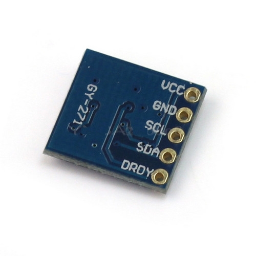
1. Barometric Sensor (BMP085)
This one:
 This is an I2C device and as such, it will be connected the same way the magnetometers are.
Obviously, this will be used for providing Atmospheric Pressure and the UI will also have a graph of the atmospheric pressure of the last 24 hours.
2. Accelerometer (ADXL345-based)
This one:
 I2C-based. Will be used for logging of the sea condition. It's a bit of a gimmick but the readings could also be used as inclinometer!
3. Noise Sensor

This will be placed under the cockpit, to the left side of the boat, as close as possible to where the outboard is fixed. That way, there's going to be a engine run-hours log! (I might add tachometer functionality at a later stage).
4. Ampere Sensor
The whole system relies on a single 12V battery for operation. I have a solar panet and charger, by using a Ampere Sensor connected straight to the battery, I will monitor charging and discharging.
The sensor that will be used is this one:
 This sensor has an analog output, which has the value VCC/2 when there is no current flowing, and it changes 185mV per Ampere flowing plus or minus the 0 Amp voltage depending on the direction of the current.
That way, I can have an indication of charging or discharging of the battery and the amperage of the current.
This sensor will by connected to the I2C ADC board that was mentioned on the previous post.
Now that I am to it, and since there are 5 analog unused inputs, I might use an input (through a voltage divider) to measure battery voltage.
That's it about the additional hardware, on the next post I will provide descriptions of system operation, both for version 1 and version 2 of software.
Regards!
But since someone can live without all of this ship computer, this is not much of a distinction, is it!
Back to the subject, the "optional" modules that will be used from day 1, have as follows:
1. Barometric Sensor (BMP085)
This one:
Obviously, this will be used for providing Atmospheric Pressure and the UI will also have a graph of the atmospheric pressure of the last 24 hours.
2. Accelerometer (ADXL345-based)
This one:
3. Noise Sensor
This will be placed under the cockpit, to the left side of the boat, as close as possible to where the outboard is fixed. That way, there's going to be a engine run-hours log! (I might add tachometer functionality at a later stage).
4. Ampere Sensor
The whole system relies on a single 12V battery for operation. I have a solar panet and charger, by using a Ampere Sensor connected straight to the battery, I will monitor charging and discharging.
The sensor that will be used is this one:
That way, I can have an indication of charging or discharging of the battery and the amperage of the current.
This sensor will by connected to the I2C ADC board that was mentioned on the previous post.
Now that I am to it, and since there are 5 analog unused inputs, I might use an input (through a voltage divider) to measure battery voltage.
That's it about the additional hardware, on the next post I will provide descriptions of system operation, both for version 1 and version 2 of software.
Regards!
Hardware Design, essential modules.
I will be using Raspberry PI's I2C interfaces for connecting the modules.
The hardware that I will be using has as follows:
1. Raspberry PI Model B, Version 2.

Since Ethernet connectivity is not needed and in order to minimize power consumption, model A could be used in field. That said, during development and testing, model B will be used.
2. The digital Compasses will be based to a HMC5883L Triple Axis Compass Magnetometer Sensor Module:

This module is I2C based.
I2C bus enables multiple devices to get connected to the master device (in this case the Raspberry PI), as shown in the following image:

The problem is that on these devices I cannot change the address, and I need to connect 2 of them!
Luckily, Raspberry PI Model B V2 (and any Model A) has available a second I2C bus, as shown in the Raspbery Schematics and described here.
So the simple solution is to connect each of the magnetometers to a different I2C bus (problem solved!).
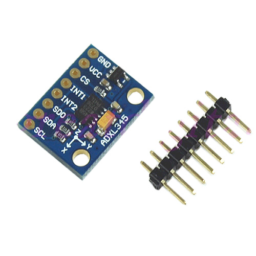
3. The existing apparent wind direction indicator produces two analogue values. In order to read them I will use an I2O-based A-to-D converter, probably this one:
Information on using and programming this module are shown here.
This is a 8 port A/D converter, for the apparent wind direction I will be using 2 (6 left, one will be used for power consumption measurement, see later!)
The relation between this values and the wind direction, will be mapped manually, by means of testing.
(UPDATE: I bought one of the above but couldn't make it work, so I opted for using a Adafruit ADS1115 instead. The Pi Chips PO11 ADC not working could be of my fault, I will investigate whenever I find time to do so...)
4. The apparent wind speed is measured by the wind cup rotor that produces a number of pulses per revolution. I intend to feed these signal to a I/O port (via a voltage divider) and use interrupts in order to measure the width of the pulse without wasting precious CPU cycles on the Raspberry.
The actual way to do it is described here.
5. The last essential module is a GPS that will communicate with the Raspberry through the Serial port.
I have bought this SUPERB GPS module:
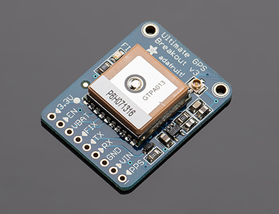

Everything needed for connecting the GPS, programming it and using it can be found here (Thanks Adafruit for everything!)
This concludes the description of the essential modules.
Ship Computer V1, Initial Hardware Design
I will be using a Raspberry PI as the heart of the system.
In order to have a working system, we need various readings, and have the corresponding sensors connected to the PI
The compulsory sensors/readings have as follows:
1. Magnetometer (Compass Sensor) for indicating the boat magnetic heading
2. Magnetometer for the mast in order to calculate mast rotation.
3. Existing apparent wind direction indicator, interfaced to Raspberry PI
4. Existing wind speed indicator, interfaced to Raspberry PI
5. GPS unit, for calculating Speed Over Ground (SoG) & Course over Ground (CoG) etc
These measurements would be logged to a database.
Using these measurements, the system would also be able to calculate the following:
1. Apparent wind direction using the mast rotation (the difference of the two magnetometers, one on the boat and the other on the mast) and the data from the apparent wind direction indicator.
2. Real Wind Direction and Real Wind Speed using data from GPS (SoG & CoG)
3. Leeway angle (from boat magnetic heading and CoG)
Additional but not critical sensors that can be added in version 1 of the ship computer could be:
1. Barometric Sensor for logging atmospheric pressure
2. 3D accelerometer for logging sea conditions
3. Current Sensor Module, that will be used for logging of battery charging and power consumption.
Ship Computer Requirements, Software Versions and functionality
OK, on my previous post I tried to sum up the situation.
Here, I will describe my needs, what I want from a ship computer.
In the next couple of posts I will describe the design, and possibly some draft of the implementation.
So, what I need.
to start with, I need to have indication of apparent wind angle. Now, one might thing that this is rather entry-level requirement, why do I have to create a custom device in order to have this indication? simply because I have a rotating mast!
the next obvious requirement is to have apparent wind speed (Kn).
This should be straightforward, at least when the wind cups rotor works!.
Then I want to have magnetic heading and course (GPS) heading, along with Speed Over Ground.
Having this measurements, it is easy to calculate True Wind Speed, True Wind Angle and leeway.
More functionality and measurements will be added in subsequent development cycles.
To sum it up, the basic info I want to have, are as follows:
1. Apparent Wind Speed
2. Apparent Wind Angle
3. True Wind Speed
4. True Wind Angle
5. Speed over ground
6. Heading
7. Course over Ground
8. Leeway angle (=heading-CoG)
I want to have realtime update for these as well as logs.
This is for version 1 of the software.
For version 2, I will provide mechanism for uploading route and waypoints so that I can have VMG and ETA calculated in real time.
The ship computer will be headless.
It will be equipped with 2 Interfaces, a WiFi setup as Access Point, and a Bluetooth.
A third interface could be added, that of a GSM/GPR/3G usb modem, in which case the Ship Computer when within 3G/GSM range, could provide Internet Access for all onboard and the same time push on a land-locked server, info on it's whereabouts and environment, providing means of fleet management (this functionality will come on Version 3 of the software).
In all software versions, the UI will be divided in Primary UI and Secondary UI.
The PRIMARY User Interface will run on a tablet (an iPad on version 1, might use android for subsequent versions).
Through the Primary User Interface, the Ship Computer will:
In Software Version 1 report to the user all values, either collected or calculated. Early version of the V1 UI could be made up as a web page created by a apache server running on the ship computer, but eventually, Version 1 UI should be a native tablet application with lifelike instruments, animated needles, etc. Version 1 UI shouldn't need two way communication, the information flow should be only from the Ship Computer (the server) to the Version 1 UI (the client).
Software Version 2 UI will be a native application built on Version 1 but will additionally provide:
In Software Version 3, the UI should be almost identical to V2, the main difference being on the software running on the ship computer itself that should be able to send regular notifications with location and other critical information (heading, speed, sea condition (see the 3D accelerometer, later in the descriptions) etc. Also V3 of the software would need server-side software for collecting these info and for presenting them to users (users could be from your mom that wants to know you are sailing safe, to the yacht charter administration office that needs to know your whereabouts in order to better assist if required)
I have started talking on the Primary UI and ended up on the V3 Server-Side software!
So let's go back to the UI!
As said before, there's going to be a SECONDARY UI too.
This will be a one way (ship computer to device) communication, that will provide quick notification on major metrics, eg Speed Over Ground (SoG), Course Heading, Wind, etc.
On VERSION 2 of Secondary UI there's also going to be VMG, Distance to next Waypoint, ETA to Next Waypoint, ETA to Finish. etc.
I have decided to implement the SECONDARY UI on a PEBBLE watch:
 The Pebble smartwatch is a fully programmable device (the SDK is freely available for download) and in contrast to most of the other SmartWatches or GPS Watches, it doesn't try to do all by itself, it doesn't even have a GPS!.
Instead, being programmable, it can communicate with a master device (server, smartphone etc) and get functionality through the other device's mechanisms.
It is slim, light, with a great paperwhite display, it's a breath of fresh air! (check out reviews on the net, eg this one).
For the secondary UI to work, the Pebble should be paired over bluetooth with the Ship Computer.
Here, I will describe my needs, what I want from a ship computer.
In the next couple of posts I will describe the design, and possibly some draft of the implementation.
So, what I need.
to start with, I need to have indication of apparent wind angle. Now, one might thing that this is rather entry-level requirement, why do I have to create a custom device in order to have this indication? simply because I have a rotating mast!
the next obvious requirement is to have apparent wind speed (Kn).
This should be straightforward, at least when the wind cups rotor works!.
Then I want to have magnetic heading and course (GPS) heading, along with Speed Over Ground.
Having this measurements, it is easy to calculate True Wind Speed, True Wind Angle and leeway.
More functionality and measurements will be added in subsequent development cycles.
To sum it up, the basic info I want to have, are as follows:
1. Apparent Wind Speed
2. Apparent Wind Angle
3. True Wind Speed
4. True Wind Angle
5. Speed over ground
6. Heading
7. Course over Ground
8. Leeway angle (=heading-CoG)
I want to have realtime update for these as well as logs.
This is for version 1 of the software.
For version 2, I will provide mechanism for uploading route and waypoints so that I can have VMG and ETA calculated in real time.
The ship computer will be headless.
It will be equipped with 2 Interfaces, a WiFi setup as Access Point, and a Bluetooth.
A third interface could be added, that of a GSM/GPR/3G usb modem, in which case the Ship Computer when within 3G/GSM range, could provide Internet Access for all onboard and the same time push on a land-locked server, info on it's whereabouts and environment, providing means of fleet management (this functionality will come on Version 3 of the software).
In all software versions, the UI will be divided in Primary UI and Secondary UI.
The PRIMARY User Interface will run on a tablet (an iPad on version 1, might use android for subsequent versions).
Through the Primary User Interface, the Ship Computer will:
In Software Version 1 report to the user all values, either collected or calculated. Early version of the V1 UI could be made up as a web page created by a apache server running on the ship computer, but eventually, Version 1 UI should be a native tablet application with lifelike instruments, animated needles, etc. Version 1 UI shouldn't need two way communication, the information flow should be only from the Ship Computer (the server) to the Version 1 UI (the client).
Software Version 2 UI will be a native application built on Version 1 but will additionally provide:
- MapView, that will enable route creation.
- Ability to upload route(s) to Ship Computer
- Ability to activate specific route
- Ability to show on map current position along with heading
In Software Version 3, the UI should be almost identical to V2, the main difference being on the software running on the ship computer itself that should be able to send regular notifications with location and other critical information (heading, speed, sea condition (see the 3D accelerometer, later in the descriptions) etc. Also V3 of the software would need server-side software for collecting these info and for presenting them to users (users could be from your mom that wants to know you are sailing safe, to the yacht charter administration office that needs to know your whereabouts in order to better assist if required)
I have started talking on the Primary UI and ended up on the V3 Server-Side software!
So let's go back to the UI!
As said before, there's going to be a SECONDARY UI too.
This will be a one way (ship computer to device) communication, that will provide quick notification on major metrics, eg Speed Over Ground (SoG), Course Heading, Wind, etc.
On VERSION 2 of Secondary UI there's also going to be VMG, Distance to next Waypoint, ETA to Next Waypoint, ETA to Finish. etc.
I have decided to implement the SECONDARY UI on a PEBBLE watch:
Instead, being programmable, it can communicate with a master device (server, smartphone etc) and get functionality through the other device's mechanisms.
It is slim, light, with a great paperwhite display, it's a breath of fresh air! (check out reviews on the net, eg this one).
For the secondary UI to work, the Pebble should be paired over bluetooth with the Ship Computer.
The secondary UI will word independantly of the Primary UI, that is, the tablet can be turned off, run out of battery, fall in the sea or whatever, the Secondary UI will still work.
(just for the record, my initial design was with the Pebbled paired on the tablet, that might have been easier to implement but the Secondary UI would be tied up to the Primary. Instead of doing so, I added a bluetooth dongle on the Raspberry PI and set up communication between Raspberry and Pebble using libpebble, a library for OSX and linux, which I installed on Raspberry.)
Anyway, enough said, will provide all info on the solution presentation on a later post.
The Ship Computer, intro
Hi all!
I set up this blog in order to keep notes on the development of what I call "the Ship Computer"
Some background notes first:
I have a Corsair F24 MKII.
This is a small trimaran, a pocket cruiser and (in other parts of the world) a racer.
It is this one:

It's great fun to sail, on the proper conditions it is much faster than what you would expect from a normal boat (i.e. monohull) of that size, and because of the nets, it has enough room to be used as a summer cruiser, sort of sailing camping that is, luxuries are what you would expect when backpack camping in the mountains. That is, the bare essentials and possibly a bit less than that!
Now, the boat has a rotating mast that is supposed to reduce drag and help with the mainsail shape on the luff. As a side effect, causes wind indicator to go bananas.
The same time, the instruments on board are not sufficient.
I have a GPS-Plotter that has north England and Scotland on rom. Living in Athens and sailing in Saronic gulf, the plotter is of not much use to me.
The GPS itself, without the plotter, has a 20-year old UI. It used to be nice if all you wanted was to get the current coordinates and plot it in a normal (paper!) map, but who does this nowadays (I don't...), adding waypoints and marking them is a total pain, and hence I tend to keep it switched off.
The wind instrument, a low-budget "NASA Clipper" is, as I said, of no use for showing wind direction and lately is also failing to show the wind speed, sometime this winter I'll take down the mast and check the transducer, hopefully it won't need replacing.
The "instrument" I use most onboard is my iPad with Navionics Marine:Europe HD app, placed in a waterproof(-ish) case.
From time to time, I also use a GPS-equipped watch (I had a Garmin 305 but it proved to be too fragile and I replaced it with a Sunnto Ambit) that I use for track recording and instant speed monitoring.
For electricity I have a single 12V battery, a 120W (nominal) semi-flexible solar panel and in case of emergency, the battery can by charged through the outboard that has a 60W charging coil.
Since I have been sailing mostly shorthanded (double-handed most of the time) I am also, when weather permits, using a Simrad tiller autopilot.
To make the long story short, I am not happy with the instruments I 've got.
I guess, I could go out and search for the instruments that fit my requirements. This has two disadvantages: 1. Cost 2. I have specific ideas on what I want and and I feel no matter how much money I spend, I won't be satisfied with the result.
So, I decided to design and build my own "Ship Computer".
Simple as that.
More on the next post...
I set up this blog in order to keep notes on the development of what I call "the Ship Computer"
Some background notes first:
I have a Corsair F24 MKII.
This is a small trimaran, a pocket cruiser and (in other parts of the world) a racer.
It is this one:
It's great fun to sail, on the proper conditions it is much faster than what you would expect from a normal boat (i.e. monohull) of that size, and because of the nets, it has enough room to be used as a summer cruiser, sort of sailing camping that is, luxuries are what you would expect when backpack camping in the mountains. That is, the bare essentials and possibly a bit less than that!
Now, the boat has a rotating mast that is supposed to reduce drag and help with the mainsail shape on the luff. As a side effect, causes wind indicator to go bananas.
The same time, the instruments on board are not sufficient.
I have a GPS-Plotter that has north England and Scotland on rom. Living in Athens and sailing in Saronic gulf, the plotter is of not much use to me.
The GPS itself, without the plotter, has a 20-year old UI. It used to be nice if all you wanted was to get the current coordinates and plot it in a normal (paper!) map, but who does this nowadays (I don't...), adding waypoints and marking them is a total pain, and hence I tend to keep it switched off.
The wind instrument, a low-budget "NASA Clipper" is, as I said, of no use for showing wind direction and lately is also failing to show the wind speed, sometime this winter I'll take down the mast and check the transducer, hopefully it won't need replacing.
The "instrument" I use most onboard is my iPad with Navionics Marine:Europe HD app, placed in a waterproof(-ish) case.
From time to time, I also use a GPS-equipped watch (I had a Garmin 305 but it proved to be too fragile and I replaced it with a Sunnto Ambit) that I use for track recording and instant speed monitoring.
For electricity I have a single 12V battery, a 120W (nominal) semi-flexible solar panel and in case of emergency, the battery can by charged through the outboard that has a 60W charging coil.
Since I have been sailing mostly shorthanded (double-handed most of the time) I am also, when weather permits, using a Simrad tiller autopilot.
To make the long story short, I am not happy with the instruments I 've got.
I guess, I could go out and search for the instruments that fit my requirements. This has two disadvantages: 1. Cost 2. I have specific ideas on what I want and and I feel no matter how much money I spend, I won't be satisfied with the result.
So, I decided to design and build my own "Ship Computer".
Simple as that.
More on the next post...
Subscribe to:
Posts (Atom)